
 Open Access
 Abstract
Nowadays, screw conveyors have been used to transport bulk materials since historical times. They are composed of a helical flight (screw), a driving shaft connected to a driving device, a casing U-trough or pipe, and so on. The principle of conveying materials relies on the friction between materials and the rotating screw or the casing. The advantages of screw conveyors are compact design, low maintenance, and the ability to transport materials continuously and safely. Screw conveyors have been used not only as bulk handling equipment to transport materials but also as parts of construction and mining machinery, e.g., underground tunneling machines, in which they are used to discharge soil or rock continuously. As volumetric devices, screw conveyor generally provide relatively precise throughput control while meeting other requirements, e.g. environmental protection. A screw feeder typically consists of a storage container (bin or hopper) coupled to a screw casing and a screw within. They are suitable for conveying dry material or grain. Although mechanical structure of screw conveyor seems very simple, mechanic of transport action is very complicated. The periodic boundary, inclination, speed of rotation, radial clearance etc. influence productivity, mass flow rate. Following theoretical studies, the radial clearance should be very small, however, in reality, the bulk material cannot go through the clearance, that makes the screw stuck and then stop. However, when the radial clearance is larger, productivity decreases very fast. In this paper, the cement is transported by screw conveyor. The experiment is done with different parameters such as speed of rotation and the radial clearance. The productivity is recorded with each change of parameters. The result from the experiment will predict the best radial clearance to transport the cement. The paper will conclude the area having high productivity and low productivity.
Introduction
The screw conveyors are very popular in transporting the bulk material such as industrial minerals, agriculture (grains), pharmaceuticals, chemicals, pigments, plastics, cement, sand, salt and food processing. They are also used for metering (measuring the flow rate) from storage bins and adding small controlled amounts of trace materials (dosing) such as pigments to granular materials or powders.
The structure of the screw conveyor is illustrated in Figure 1 . The main components of the screw conveyor consist of:
a hopper and a bin.
Screw casing.
Rotating screw.

The structure of rotating screw and screw casting affect the productivity much. The radial clearance between screw and casing plays an important role in ensuring productivity.
In Алферов К. (1955) 1 , the clearance is very small about few millimeters. It must be small to prevent the hulk material to go through the gap. However, in reality, this clearance will make the material stuck when the rotational speed increases. The reason of the stuck problem is inertia of material. To decrease stuck problem, the radial clearance will increase. However, the larger clearance is, the more productivity reduces. The problem of clearance is to choose an optimal value of clearance.
In Alma Kurjak (2005) 2 , The clearance is a big influence on screw capacity. The reasonable clearance depends on size of particles. Particles larger than 250 µm are usually relatively free flowing, but as size falls below 100 µm powder become cohesive and flow problems are likely to occur. Powders having a particle size less than 10 µm are usually extremely cohesive. The relation between size of particles and clearance is non-linear. This relation depends on cohesiveness of material, size.
In Yoshiyuki Shimizu1 and Peter A. Cundall (2001) 3 Yoshiyuki Shimizu1 and Peter A. Cundall show that clearance affect the net power. When clearance increase, the net power will more steady. However, the ratio between overall power and net one increase. The clearance depends on the friction coefficient between particles and screw components, and the material properties. To increase the productivity, the shaft will rotate with a threshold speed and then the particles reach equilibrium, the screw and the driving shaft are both rotated through three complete rotations at the specified, constant angular velocity, while the casing remains at rest.
A.W. Roberts in A.W. Roberts (1999) 4 said the enclosed screw conveyor became more efficient at higher rotational speeds as a result of the reduced rotational speed or vortex motion of the bulk material. This advantage is usually more than offset by the decrease in ‘fullness’ of the conveyor that accompanies higher operating speeds. As the rotational speed of the conveyor increases, the rotational or vortex motion decreases up to a limiting value making for a more efficient conveying action. However, when a gravity feed system into the screw intake is employed, the feed rate cannot match the potential conveying capacity, and a reduction in ‘fullness’ occurs. The clearance will be chosen at least 1.5 times larger than the maximum particle size in order to prevent jamming of particles in the clearance space leading to particle attrition and increased energy loss. To prevent excessive slip back and loss of efficiency at higher angles of elevation, the clearance needs to be limited to a maximum value of about three times the maximum particle size.
To increase the power of handling, the speed of rotation is raised to 1000 round per minute. With that speed, the angle of incline and clearance will affect mass flow rate 6 , 5 . This affection is difficult to calculate. Thus, the experiment will be done to determine parameters to achieve the optimal mass flow rate.
In this paper, the screw conveyor is used to handle the cement. Some parameters are designed with referring to Алферов К. (1955) 1 , the radial clearance is calculated and experimented to find an optimal value to obtain the largest productivity. The next part is divided into 4 parts consisting of the theory of power, method, result and discussion. The conclusion will summarize the application in reality.
MODEL DESCRIPTION
In the screw conveyor, the productivity is a very important parameter 1 . It can be easily illustrated in .
maximum theoretical volumetric throughput with conveyor running 100% full and the bulk material moving axially without rotation.
: volumetric efficient
: crew diameter (m)
: core or shaft diameter (m)
: Pitch (m).
: angular velocity of screw (r/s).
: Radial clearance (m).
: Thickness of screw blade (m).
The productivity efficiency of a crew conveyor consists of two components as follows.
With the productivity is given in , the angular velocity of main shaft is
where outer radius.
g : gravitation acceleration.
N : Rotation speed (round/minute).
The shows the screw conveyor of large diameter will attain the high productivity with low rotational speed when comparing with the conveyor of small diameter.
 1" width="300" height="200">
With the volumetric given in , the mass throughput of a screw conveyor in kg/s is showed as follows.
where : bulk density, kg/m 3 .
The bulk material density will increase when material is compressed in conveyor and the density will approach a maximum limiting value 2 . The bulk density is a function of major consolidation pressure for a typical cement sample.

A particle in a vertical crew conveyor will have a velocity diagram as Figure 3 . is the screw velocity when it rotates. is particle’ s relative velocity with respect to the screw surface. is the absolute velocity of the particle by the helix angle .
To be simple in calculation, the velocity diagram ( Figure 3 ) will be unfolded in Figure 4 . The velocity diagram in which the absolute velocity is separated into two components, the useful conveying velocity and the rotational component . The helix angle a of the screw flight is smaller at the outer of the flight to the shaft. Similarly, angle l also vary in the radial direction from the outside to the shaft. The variation of with radius illustrates the vortex motion in the screw. The variation of with radius describes the vortex motion in the screw. It is expressed by

The value “n” is the vortex index 2 . It often equal zero, as a result, velocity component is constant and does not vary with the radius.
Following Figure 5 when actual conveying velocity is expressed as a ratio of maximum theoretical conveying velocity it will provide a measure of conveying efficiency allowing for losses resulting from the rotational or vortex motion. It will be expressed that
In the conveying operation, it is necessary to determine the variation of the path helix angle l as a function of the radius and rotational speed of conveyor. As said above, is constant and doesn’t vary with the radius. To simplify the analysis of the screw conveyor, the rotational mass and resultant forces at the effective radius is lumped as follows.
where outside radius of screw flight.
Inner radius of radius.
The helix angle of the screw flight corresponding to is:
where p : pitch.
D = = screw flight diameter
The helix angle of the path and the speed of rotation of the shaft have relationship studied in Алферов К. (1955), Alma K. (2005), Yoshiyuki S. and Peter AC. (2001) 3 , 2 , 1 . With special case of the effective radius, the relationship between specific rotational speed and the helix angle is expressed as follows.
where
Friction angle for screw surface;
: 0.4.
: Fill ratio or fullness.
: Friction coefficient for bulk material on casing surface.
From the equation (10), the vortex efficient is shown as follows
where effective helix angle –
Effective helix angle of the path –
Research 4 , 3 , 2 , 1 showed that for horizontal screw conveyor, the angle (in Figure 4 ) is zero. That means the helix angle of the path is independent of the screw speed and is given by
This relationship may also be assumed for screw conveyors operating at low angles of elevation up to say, The conveying or vortex efficiency derived from and is expressed by
The analysis for operation at any elevation angle q is more complex. For inclination angles ranging from 30 0 to 90 0 , may still applied, but in the modified form
The function and need to be defined. When has been determined, then is used to determine Hence the throughput may be calculated.
An alternative, somewhat empirical approach solution is as follows.
(a). Compute the conveying or vortex efficiency for a vertical conveyor in accordance with ,
(b). Compute the conveying efficiency for a horizontal conveyor using .
(c). Interpolate the conveying efficiency for inclination angle q as follows.
When the screw conveyor operates, there are two torques: the torque due to the bulk on the shaft and torque per pitch due to the bulk solid on the flight face . The torque per pitch is determined from the following equation
where friction angle for bulk solid on screw surface.
Effective radius.
Effective helix angle.
L : length of screw conveyor.
p : pitch.
The torque due to the bulk solid on the shaft is:
where
The total torque on the shaft is:
Thus, the power for the motor is:
where N: round per minute.
drive efficient.
METHOD, RESULT AND DISCUSSION
Cement is the most frequently used material in construction today. Slightly more than a ton of concrete is produced every year for each person on the planet, approximately 6 billion tons per year. It is a versatile material and can be molded to just about any shape. Cement is also strong, inexpensive, and easy to make. In this part, the cement will be experimented with screw conveyor whose parameters consist of radial clearance, angular speed and then the productivity will be measured. The cement characteristics can be shown as follows:
Particle shape: Shape analysis will also provide information on parameters such as equivalent shape factor and aspect ratio, both of which determine the cements flow-ability. The cements particle size is now seen as critical for the determination of the quality of the cement. As finer particle size will result in a greater surface area, cement manufactures control particle size as this parameter directly affects the cement’s compressive strength and curing speed. Particles larger than 50 micron cannot be fully hydrated, while particles smaller than 2 micron cause exothermal setting in the final product. In this experiment, the cement has medium size of 15.4 mm 7 .

Angle of repose : The angle of repose, or critical angle of repose, of a granular material is the steepest angle of descent or dip relative to the horizontal plane to which a material can be piled without slumping. At this angle, the material on the slope face is on the verge of sliding. Following Piotr Kulinowski et al. 8 , cement has an angle of repose of 20 degrees.
Hausner Ratio, A.W. Roberts (1999) 4 : the Hausner ratio is derived from the quotient between tapped density (TD) and apparent density (AD). Tapped density was measured using Stamp volume meter. The Hausner ratio of cement measured is 1.27.
Conveying length : in this experiment, the conveying length is 3 meters.
Flow rate: Flow rate is the time in seconds, which an amount of 50 g dry powder needs to pass the aperture of standardized funnel. Flow rate of cement is 35 seconds 9 .
Clearance: At a large clearance a back flow of bulk material opposite to the conveying direction occurs followed by reduction in conveyor capacity. However, if clearance is small milling and jamming can take place between screw and casing. Clearance is also necessary for smooth running of the conveyor. Therefore, it is important to find the smallest clearance at which no milling and jamming process takes place.
Before make the experiment, the flow weight, moment on the shaft and the motor will be calculated and then the result will be compared with experimental data. The discussion will give remarks about the difference between theory and experiment.
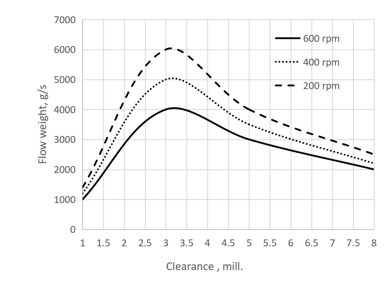
Firstly, the moment on the shaft will be calculated from equation (20). This moment will help to obtain a durable shaft, to ensure to work for a long time. Then, based on the equation (21), the power of motor will be determined. And lastly, the flow weight will be calculated from equation (8). The parameters in the formula will be directly measured from the model of conveyor. The results are shown in Figure 6 . Where, the dashed line shows the angular speed of 200 round p er minute, dotted line 400 and solid line 600. Next part, the real conveyor will be experimented and then, the result of experiment will be shown.

In the experiment, the angular speed of main shaft will be changed by a control system. The speed will be also from 100 to 700 round per minute. Three screw conveyors with different outer diameters are prepared to produce 4 different radial clearances 1, 3, 5 and 8 millimeters. The diameter of shaft and the casing are all fixed in experiment. Two parameters do not need to change because in this experiment, the effect of clearance on the productivity is being concerned.
The Figure 7 expresses the flow weight versus radial clearance. The dash line show the shaft rotates 200 round per second, the dot line is 400 and the last one is 600. Bigger t he clearance is, the more back flow it is. However, when the clearance is smaller than 3 millimeters, the jamming problem occurs and the motor will stop and then start. As a result, the medium shaft speed reduces a half. Thus, the flow weight is so low and the motor is often full load, that causes damage of the screw conveyor.
From the result of experiment and theory, some discussion can be given:
The theory formula will not coincide with experiment result at the clearance that is smaller than 3 mm. The reason can be explained that the theory formula doesn ’ t calculate the jamming between casing and screw. Thus, the productivity decrease and make the conveyor damageable.
When the clearance is bigger than 3 mm, the jamming phenomenon can be neglected, thus the theoretical results seem same as the real results.
The clearance should not be so large. the productivity will decrease so fast when the clearance becomes larger.
CONCLUSION
The clearance is an important parameter to increase productivity. Following the theoretical formula, the result of productivity in the small clearance is not exact because the jamming phenomenon is not dealt with. The experiment results showed that the clearance should be 1.5 to 2 times of size of particle but the minimum clearance is 3 millimeters. With cement conveying, the clearance should be 3 to 5 millimeters.
Abbreviation
HCMUT : Ho Chi Minh city University of Technology
TD : tapped density
AD : apparent density
Conflict of interest
Author ensure that there is no conflict of interest in this paper.
Authors’ contribution
Tung T. Luu did works in this paper.
References
- К Алферов. Бункерные установки. Проектирование, расчет и эксплуатация. . 1955;:. Google Scholar
- Kurjak Alma. The vertical screw conveyorpowder properties and Screw conveyor design. . 2005;:. Google Scholar
- Shimizu1 Yoshiyuki, Cundall Peter A. Three-Dimensional Dem Simulations Of Bulk Handling By Screw Conveyors. Journal Of Engineering Mechanics. 2001;:. Google Scholar
- Roberts A W. The influence of granular vortex motion on the volumetric performance of enclosed screw conveyors. Powder Technology. 1999;:. Google Scholar
- Philip J, Owen Paul W, Cleary -. Screw conveyor performance: comparison of discrete element modelling with laboratory experiments. Progress in Computational Fluid Dynamics. 2010;10:. Google Scholar
- Owen P J, Cleary P W. Prediction of screw conveyor performance using the Discrete Element Method (DEM). Powder Technology. 2009;:. Google Scholar
- Ankersmid Particle Size and Shape Analysis of Cement Samples. APPLICATION NOTE 3.2. 2005;:. Google Scholar
- Kulinowski Piotr, Kasza Piotr. Properties Bulk Solids. Department of Mining, Dressing and Transport Machines. ;:. Google Scholar
- Akram H, Abed Abdulmunem R, Abdulmunem -. Investigation of combination between latent and sensible heat storage materials on the performance of flat plate solar air heater. The Iraqi Journal For Mechanical And Material Engineering. 2018;18(1):63-77. Google Scholar