 Open Access
 Abstract
The understanding of the diesel combustion mechanism is crucial in the optimization of fuel combustion efficiency and emission formation, a control method of the fuel injection timing and an experimental combustion measurement on a constant volume combustion chamber (CVCC) were carried out. A pre-combustion technique has been used to burn combustible gas mixtures, including acetylene, oxygen, and nitrogen, to generate diesel engine conditions. The created combustion pressure in CVCC was quantified by a piezoelectric transducer pressure sensor, and a microcontroller processed the consecutively recorded pressure data to determine the desired fuel injection timing, like diesel engine conditions, by real-time synchronization. Then the diesel combustion pressure, rate of heat release, and ignition delay were analyzed under conditions of fuel injection pressure, ambient temperature, and oxygen concentration corresponding to 1200 bar, 1000 K, and 21%, respectively. The obtained results revealed that the fuel injection control algorithm met the desired operating pressure conditions precisely within 2.7% in error. Moreover, the observations from the combustion pressure and rate of heat release analysis showed a similar development trend as compared to diesel combustion.
Introduction
Many solutions have been studied to increase fuel efficiency, engine power, and reduce pollutant emissions from diesel engines. Research directions such as Low-temperature Combustion (LTC), Homogeneous Charge Compression Ignition (HCCI), Reactivity Controlled Compression Ignition (RCCI), and their combination with Common Rail electronic fuel injection technology have been employed throughout. 1 , 2 , 3 , 4 However, the complexity and challenges of experimentally investigating the influence of specific operating conditions (compression ratio, flame development, fuel injection pressure, temperature distribution, and soot formation mechanisms) on the diesel engine combustion process pose significant hurdles to achieving these objectives.
In order to address these issues, several experimental systems have been developed. The Rapid Compression and Expansion Machine (RCEM) system, as studied by V. Chau et al., 5 enables the simulation of compression and expansion processes within an internal combustion engine to investigate the combustion process by varying various experimental conditions (compression ratio, pressure, and temperature of the combustion environment, injection pressure, etc.). The Constant Pressure Flow Rigs (CPFR) system, studied by Allen Parker et al., 6 allows the maintenance of constant pressure during the combustion process to analyze the structural characteristics of unreacted and reacting regions during combustion, as well as measuring the penetration and propagation velocity of the fuel jet. Each experimental system has its own advantages and limitations in the study of fuel combustion processes. The operational characteristics of these devices are presented in the work by Baert et al. 7 Among these, the Constant Volume Combustion Chamber (CVCC) optical approach is noted for its numerous advantages in observing the formation and combustion processes of fuel mixtures, by altering parameters such as pressure and temperature inside the combustion chamber, and in conjunction with the Common Rail Direct Injection (CRDI) fuel injection system. 8 , 9
The CVCC system is based on the pre-combustion technique, which ignites the combustible gas mixture to create a combustion environment similar to diesel engines. The combustible gas mixture used varies among studies, with acetylene, ethylene, or hydrogen being employed as the ignition fuel. 10 , 11 , 12 Baert et al. 7 utilized the “Repeatability of the Pre-combustion Process” method, performing multiple pre-combustions under the same condition to accurately determine the fuel injection timing and achieve the desired temperature and pressure in the environment. In the study by Zhicheng Shi et al., 13 the injection system was combined with a Kibox unit controller using ECKA2.0 operating software. However, these studies did not provide a detailed description of the real-time synchronous control algorithm for electronic fuel injection.
This research develops a method for determining fuel injection timing using a real-time synchronized algorithm during the pre-combustion phase in the constant volume combustion chamber at pressure conditions of 43 bar and O 2 concentration of 21%. Subsequently, fuel injection experiments were conducted at 1200 bar pressure conditions, and the diesel combustion process characteristics were recorded by the CVCC system. Simultaneously, the analysis of diesel fuel combustion characteristics was carried out under the mentioned conditions.
MATERIAL AND METHODS
Simulation method of diesel conditions in CVCC
The pre-combustion technique can be employed to model the diesel engine environment during the late compression stroke, characterized by high gas pressure and temperature conditions, prior to the initiation of diesel fuel injection timing inside the CVCC. The underlying concept of the pre-combustion technique is visually depicted in Figure 2 . This technique includes two main phases: the premixed combustion stage and the cool-down stage. The combustible gas mixture, containing acetylene ( C 2 H 2 ), oxygen ( O 2 ), and nitrogen ( N 2 ), is fed to the CVCC in a determined percentage through the solenoid valves. This research employs acetylene as the combustible gas instead of ethylene or hydrogen because it offers relatively high heat content and limits the amount of water vapor in the combustion products, thereby mitigating the phenomenon of water vapor condensation on the surface of quartz windows. The sequence starts with C 2 H 2 , followed by N 2 , and finally O 2 to avoid auto-ignition of the combustible gas mixture since the molecular structure of C 2 H 2 has a triple bond between two C atoms, which is unstable and can break at pressures above 2 bar, resulting in acetylene detonation. 14 The percentage of each partial gas was controlled by a Matlab program, following the chemical reaction equation (1) to generate an ambient environment with target residual oxygen contents of 21 mol%, equivalent to no EGR ratios. For the diesel combustion phase, the work picked 3.5% acetylene, 29.38% oxygen, and 67.12% nitrogen by volume for producing 21% residual oxygen content, high pressure and temperature. For cases with residual oxygen contents of 15 mol% or 10 mol%, the gas mixture composition follows equations (2) and (3) respectively. The produced temperature and pressure are considerably higher than those of the diesel engine’s operating conditions after the chemical reaction, and the cooling-down stage begins. The high temperature and pressure were decreased at this phase as a result of heat transfer via the chamber wall and quartz windows, and the ambient combustion environment of the diesel engine operating conditions was established. This method has also been used in other studies. 15 , 16 , 17 , 18 , 12
The method calculates combustion characteristics
Apparent heat release rate (AHRR)
The apparent heat release rate (AHRR) was determined from pressure rise through the recorded data of a piezoelectric transducer pressure sensor after burning an injected fuel amount according to the first rule of thermodynamics 19 and expressed in equation (2):
where is the heat release rate (J/s), is the specific heat ratio (1.35), P is the pressure inside the cylinder (Pa), and V is the chamber volume (m 3 ). In this study, the CVCC has been used for conducting the experiment. Therefore, the heat release rate for CVCC is simplified in equation (3). 20 21
Ignition Delay (ID)
The interval time, counted from the start of injection (SOI) to the start of combustion (SOC), was recognized as an ignition delay. In this work, ignition delay was calculated from the triggered injector driver signal until the time when the heat release rate curve switched from a negative to a positive value. 22
Bulk gas temperature of combustion products
Where T int , P int are the initial temperature (K) and pressure (bar) of the unburned premixed charge gas, T 2 , P 2 are the ambient temperature (K) and pressure (bar) of the desired injection condition, and is a fraction of the molar mass of the unburned premixed charge after and before the igniting occurrence.
Method of real-time synchronizing in fuel injection timing determination
The desired ambient pressure, initial combustible gas pressure, and fuel injection duration were set up on the operating control program. After ignition, the ambient pressure signal will be recorded and amplified by a Kistler 5010 charge amplifier before being transmitted to the data acquisition and control (DAC) system for processing. The allowable injection range, auto-identified as the pressure history curve detects a pressure greater than that of the desired value by 5 bar, is essential to prevent fuel injection during the pre-combustion phase. Then, the microcontroller will control the fuel injection when the ambient pressure reaches the desired value within the allowable injection range. Figure 3 illustrates the overall procedure for auto-determining the start time of fuel injection.
EXPERIMENTAL SETUP AND TESTING CONDITIONS
Experimental setup
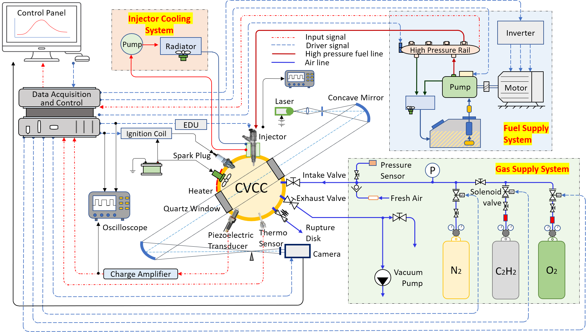
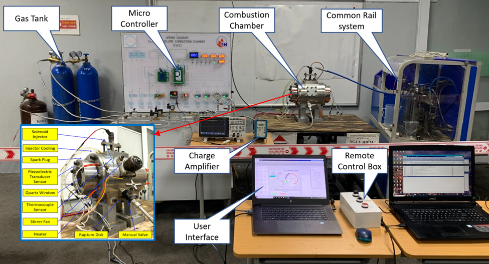
Figure 4 shows the detailed schematic layout of the constant volume combustion chamber (CVCC) system. The system comprises five main components: the CVCC chamber, gas supply, high-pressure fuel supply, data acquisition and control (DAC), sensors, and ignition system. Additionally, several sub-systems are equipped to ensure the operation of the CVCC system. The CVCC chamber was made from 304 alloy steel with a diameter of 80 mm, a stroke of 109 mm, and a volume of 546,1 cm 3 . The chamber has six main ports to install the components: intake-exhaust valves, spark plug, injector, rupture disk, stirrer fan, and piezoelectric transducer pressure sensor ( Figure 5 ). Two quartz windows on the sides of the chamber were fabricated from natural quartz silica with a diameter of 110 mm and a thickness of 85 mm, which is capable of a high UV transmittance down to 190 nm. 23 The test procedure begins with opening the exhaust valve control, and a vacuum pump evacuates the combustion products. A stirrer fan is employed to mix the gas mixture for approximately 15 seconds, creating a more homogeneous condition before initiating the pre-combustion technique. The combustible gas mixture is burned by the plasma of the spark plug. Finally, the high-pressure diesel is injected into the CVCC cylinder, combined with the ambient combustion environment after the pre-combustion technique. Then the combustion of the diesel fuel starts. In-chamber pressure is measured using an AVL GU12P piezoelectric transducer pressure sensor (Austria). The signal from this sensor is coupled with a Kistler 5010 charge amplifier (Germany).
Experimental testing conditions and fuel properties
Table 1 shows the detailed experimental operating conditions in this work. Diesel fuel (DO 0.05S) was used as the main fuel for the combustion phase. The used fuel characteristics are displayed in Table 2 . 24 A high-pressure common rail pump was employed to generate a fuel pressure of 1200 bar, while the injection duration was fixed at 2.0 ms. The diesel fuel injection control module was used to control the single-hole solenoid injector (Bosch CRIN2) with a nozzle orifice diameter of 0.33 mm. For this study, the ambient combustion environment equivalent to that of a diesel engine was selected for experimental purposes under 21%–15%–10% oxygen concentration and 51–43–34 bar of ambient pressure.
RESULTS AND DISCUSSIONS
Temporal auto-determination of injection timing from pre-combustion pressure curve
Figure 6 illustrates the pressure evolution in the CVCC after the spark plug signal is activated under experimental conditions of 14 bar initial mixture pressure, 21% oxygen concentration after ignition, and 43 bar at the time of fuel injector activation by using the real-time synchronized pressure determination algorithm. The results indicated that the maximum pressure value recorded by the equivalent sensor was 70.2 bar within 80 ms from the ignition signal. The DAC system controlled by the microcontroller continuously recorded data and automatically triggered the solenoid injector when the pressure dropped to around 43 bar at 845 ms. The results demonstrated that the DAC system effectively captured combustion process data and precisely auto-controlled fuel injection into the combustion chamber at the desired ambient pressure via the real-time synchronization control method.
Figure 5 . Integrated graph of pressure, ignition signal, and injection signal at pressure conditions of 43 bar and O 2 concentration of 21%, fuel injection pressure of 1200 bar
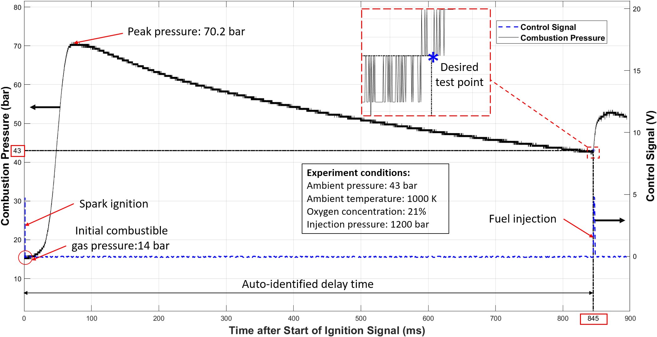
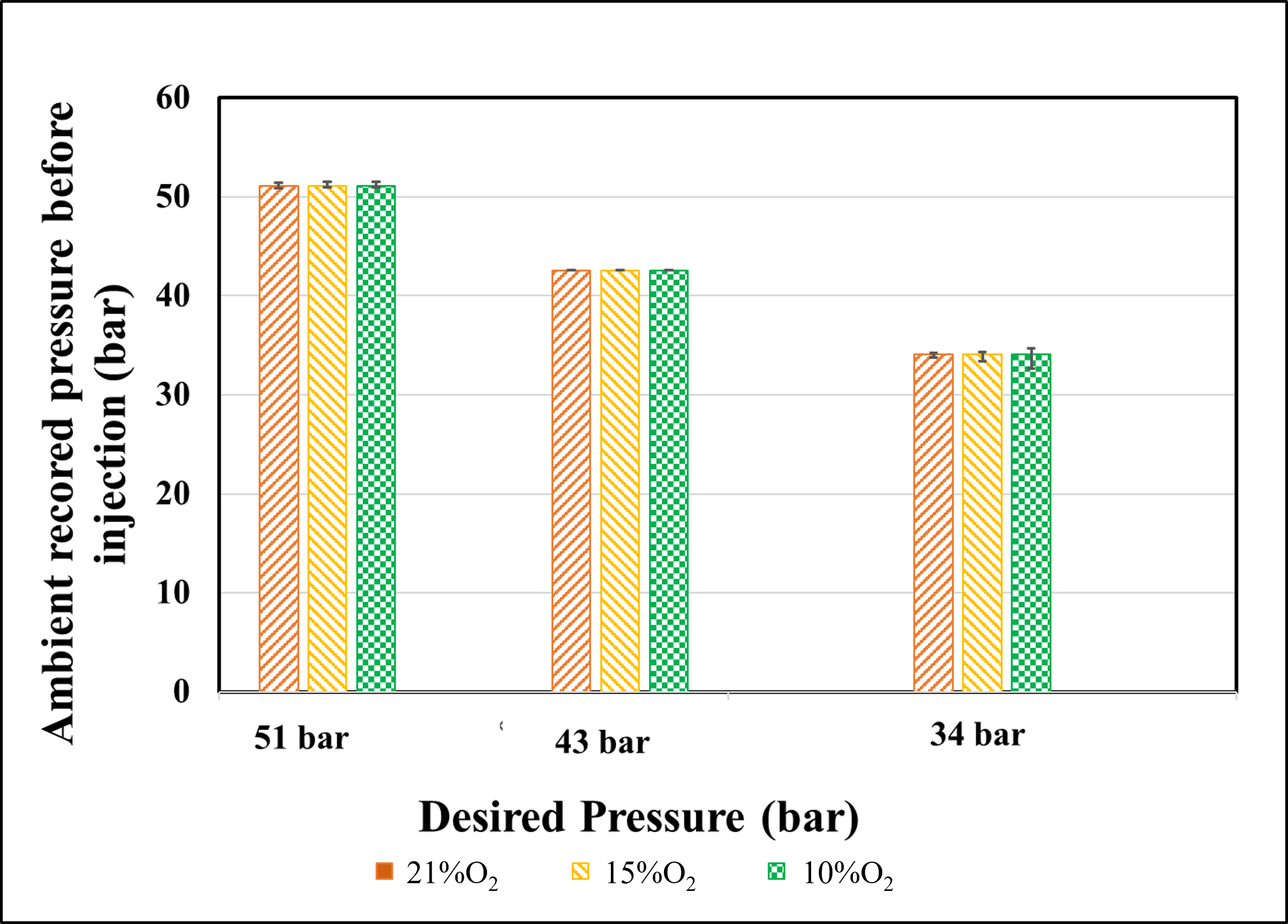
Figure 7 presents the results of the auto-identified delay time for the fuel injector signal, which is the time elapsed from the ignition trigger pulse to the injection-activated pulse. The values were averaged from twenty experimental runs at each desired ambient pressure condition, with varying oxygen concentrations of 21%, 15%, and 10%. The results demonstrated that, with the implemented algorithm, the auto-identified delay time from the twenty experimental runs at each condition exhibited differences with a maximum error of less than 6%. Moreover, Figure 8 revealed that the DAC system precisely identified the fuel injection timing with an ambient pressure error within 2.7% and a standard deviation of less than 0.65 bar, indicating its stable operation.
Figure 6 . The accuracy evaluation of real-time synchronization algorithm for fuel injection control via auto-identified delay time
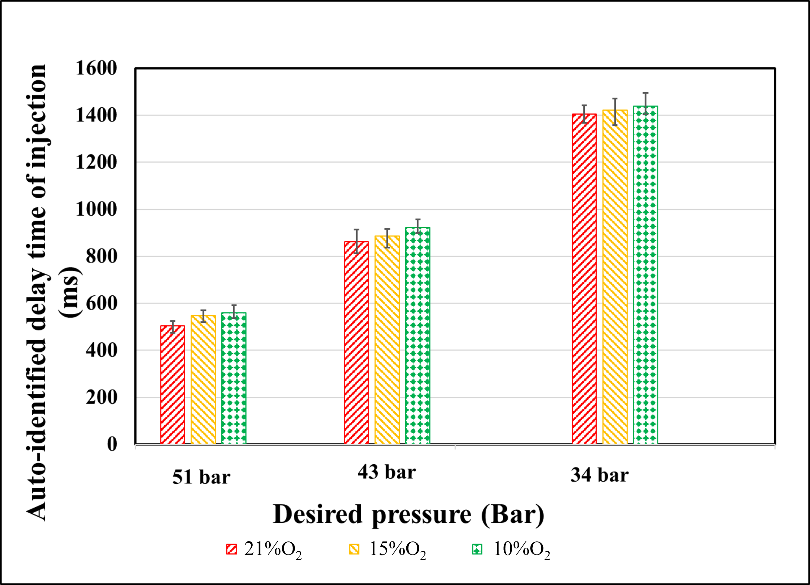
Figure 7 . The accuracy evaluation of real-time synchronization algorithm for fuel injection control via ambient recorded pressure
Diesel combustion characteristics
Figure 9 depicts the combustion pressure and heat release rate results of diesel fuel in the constant volume combustion chamber (CVCC) system at pressure conditions of 43 bar and O 2 concentration of 21%. After energizing the injector from the DAC system, the pressure inside the chamber initially slightly decreases. Subsequently, the fuel begins to auto-ignite within the CVCC, leading to a rapid increase in combustion pressure, peaking at 54.7 bar at 14.8 ms and then gradually declining. This pressure development trend is similar to several studies on the combustion process of various types of fuels in the CVCC system. 25 , 26 , 27
The combustion pressure curve in the CVCC chamber shows a significant difference compared to the combustion pressure curve in a real engine. In an actual diesel engine, when the pressure reaches its peak, it quickly decreases. The main reason for this is the peak cylinder pressure occurring at the top dead center (TDC), after which the piston moves to the bottom dead center (BDC). This movement leads to an increase in the volume of the chamber, resulting in a rapid decrease in combustion pressure. On the other hand, in the CVCC chamber, the volume remains constant, and the reduction in pressure inside the chamber is solely based on the decrease in temperature within the chamber. The curve of combustion pressure in the study is also found in the research conducted by D. Qi et al. 28 and H. Liu et al. 29
The characteristics of the heat release rate were calculated from the combustion pressure data. Figure 8 details the heat release rate of diesel fuel at an ambient pressure of 43 bar. At the beginning of the ignition delay period (IDP), the rate of heat release dips into negative values, attributable to the cooling effect of fuels. The evaporation of fuel into the hot environment causes a decrease in the HHR curves. 30 , 31 The IDP of diesel fuel in the CVCC lasts for 0.73 ms. During the IDP, ambient air is mixed into the fuel spray, forming a premixed air-fuel combination that subsequently self-ignites, representing the premixed combustion phase. As AHRR increases, at around 1.5 ms, a kink appears on the graph. This may be due to pressure wave oscillations when the fuel spray plume impinges on the chamber wall (opposite the injector), and the continuously injected fuel creates dynamic variations in fuel particles, causing the fuel to scatter throughout the chamber. This pressure wave partly quenches the ongoing combustion of the fuel particles. Additionally, the flame contacting the cold chamber wall contributes to flame quenching and slows down the combustion process. The heat release rate during this period sharply increases and reaches a peak of approximately 490 J/ms within 3.42 ms. Afterward, the heat release rate slightly decreases, attributed to the depletion of the air-fuel mixture from the premixed combustion stage and the turbulent effect within the chamber. The elevated heat inside the chamber, generated during premixed combustion, promotes the atomization and vaporization processes of the fuel spray jet, combine with the swirl motion of air inside the chamber, the diffusion combustion phase officially commences. Diesel combustion continues until all remaining fuel is consumed and the heat release rate returns to zero. The observed trend of heat release rate in CVCC aligns entirely with findings from studies worldwide. 32 , 33 , 34

Conclusions
In this paper, developing a method for determining the fuel injection timing and investigating the diesel combustion characteristics have been accomplished in a constant volume combustion chamber (CVCC) system. Based on the testing findings, the conclusions can be stated as follows:
The real-time synchronizing method in fuel injection timing determination enables the CVCC system to achieve accurate and stable operation, maintaining the ambient pressure error within 2.7% and a standard deviation of less than 0.65 bar.
Diesel combustion characteristics consisting of the combustion pressure, heat release rate, and ignition delay showed suitable analyzed results under simulated diesel engine operating conditions in the CVCC system.
ABBREVIATIONS
AHRR: Apparent Heat Release Rate
AIR: Allowable Injection Range
HRR: Heat Release Rate
CVCC: Constant Volume Combustion Chamber
LTC: Low-temperature Combustion
HCCI: Homogeneous Charge Compression Ignition
RCCI: Reactivity Controlled Compression Ignition
RCEM: Rapid Compression and Expansion Machine
CPFR: Constant Pressure Flow Rigs
CRDI: Common Rail Direct Injection
SOI: Start of Injection
SOC: Start of Combustion
DAC: Data Acquisition and Control
TDC: Top Dead Center
BDC: Bottom Dead Center
IDP: Ignition Delay Period
Competing Interests
The authors wish to confirm that there are no know conflicts of interest associated with this publication and there has been no significant financial support for this work that could have influenced its outcome.
Authors' Contributions
All authors contributed to the research, participated in algorithm development, and conducted CVCC experiments. All members contributed equally to this study.
References
- Azimov U.B., Kim K.S., Jeong D.S., Lee Y.G.. Evaluation of low-temperature diesel combustion regimes with n-Heptane fuel in a constant-volume chamber. International Journal of Automotive Technology. 2009;10(3):265-276. Google Scholar
- Hasan M.M., Rahman M.M.. Homogeneous charge compression ignition combustion: Advantages over compression ignition combustion, challenges and solutions. Renewable and Sustainable Energy Reviews. 2016;57:282-291. Google Scholar
- Yıldız M., Çeper B.A.. A comparative study on gasoline/diesel-fueled RCCI combustion at different premixed ratios and high-EGR diesel CI combustion in an IC engine under low load conditions. Fuel. 2022;324:124596. Google Scholar
- Agarwal A.K., Singh A.P., Kumar V.. Particulate characteristics of low-temperature combustion (PCCI and RCCI) strategies in single cylinder research engine for developing sustainable and cleaner transportation solution. Environmental Pollution. 2021;284:117375. Google Scholar
- Vo C., Charoenphonphanich C., Karin P.. Effects of variable O2 concentrations and injection pressures on the combustion and emissions characteristics of the petro-diesel and hydrotreated vegetable oil-based fuels under the simulated diesel engine condition. Journal of the Energy Institute. 2018;91(6):1071-1084. Google Scholar
- Parker A., Wanstall C.T., Reggeti S.A.. Simultaneous rainbow schlieren deflectometry and OH* chemiluminescence imaging of a diesel spray flame in constant pressure flow rig. Proceedings of the Combustion Institute. 2021;38(4):5557-5565. Google Scholar
- Baert RSG., Frijters PJM., Somers B.. Design and operation of a high pressure, high temperature cell for HD diesel spray diagnostics: Guidelines and results. SAE Technical Papers, SAE International. 2009;:. Google Scholar
- Yao C., Hu J., Geng P.. Effects of injection pressure on ignition and combustion characteristics of diesel in a premixed methanol/air mixture atmosphere in a constant volume combustion chamber. Fuel. 2017;206:593-602. Google Scholar
- Fujimoto H.G., Higashi K., Yamashita T., Senda J.. Effects of Ambient Temperature and Oxygen Concentration on Soot Behavior in Diesel Flame. SAE Technical Paper. 2005;:. Google Scholar
- Srichai P., Karin P.. Design Concept of Biodiesel Direct Injection Constant Volume Combustion Chamber. . 2012;:. Google Scholar
- Tien N.M., Thanh N.L.C, H.H.Phi Dong N.V.. A study on the influence of ignition energy on ignition delay time and laminar burning velocity of lean methane/air mixture in a constant volume combustion chamber. UD-JST. 2021;19(12.1):1-4. Google Scholar
- Ogawa H., Shibata G.. Visualization analysis of diesel combustion with water and diesel fuel emulsified blend in a constant volume chamber vessel. SAE Technical Papers, SAE International. 2014;:7. Google Scholar
- Shi Z.. Effect of injection pressure on the impinging spray and ignition characteristics of the heavy-duty diesel engine under low-temperature conditions. Appl Energy. 2020;262:114552. Google Scholar
- Phan A.M.. Development of a Rate of Injection Bench and Constant Volume Combustion Chamber for Diesel Spray Diagnostics. . 2009;:. Google Scholar
- Liu Y., Li J., Jin C.. Fuel spray and combustion characteristics of butanol blends in a constant volume combustion chamber. Energy Convers Manag. 2015;105:1059-1069. Google Scholar
- Ma Y., Huang S.. Ignition and combustion characteristics of n-pentanol–diesel blends in a constant volume chamber. Appl Energy. 2017;185:519-530. Google Scholar
- Hwang J., Park Y.. Fuel temperature influence on spray and combustion characteristics in a constant volume combustion chamber (CVCC) under simulated engine operating conditions. Fuel. 2015;160:424-433. Google Scholar
- Wu H., Nithyanandan K.. Spray and Combustion Characteristics of Neat Acetone-Butanol-Ethanol, n-Butanol, and Diesel in a Constant Volume Chamber. Energy & Fuels. 2014;28(10):6380-6391. Google Scholar
- Heywood J.B.. Combustion in compression-ignition engines. . ;:851. Google Scholar
- Marasri S.. Combustion characteristics of hydrotreated vegetable oil-diesel blends under EGR and low temperature combustion conditions. International Journal of Automotive Technology. 2019;20(3):569-578. Google Scholar
- Kook S., Pickett L.M.. Effect of fuel volatility and ignition quality on combustion and soot formation at fixed premixing conditions. SAE International Journal of Engine. 2010;2(2):11-23,. Google Scholar
- Wu Y., Huang R.. Effects of the exhaust gas recirculation rate and ambient gas temperature on the spray and combustion characteristics of soybean biodiesel and diesel. Proceedings of the Institution of Mechanical Engineers, Part D: Journal of Automobile Engineering. 2012;226(3):372-384. Google Scholar
- Liu H., Yao M.. Study of biodiesel combustion in a constant volume chamber with different ambient temperature and oxygen concentration. SAE Technical Papers. 2011;:. Google Scholar
- Petrolimex Diesel Fuel Specifications. TCCS 03:2015/PLX. 2016;:. Google Scholar
- Liu H., Lee C.F.F.. Combustion characteristics and soot distributions of neat butanol and neat soybean biodiesel. Energy and Fuels. 2011;:3192-3203. Google Scholar
- Lee T.H., Lin Y.. Characterization Spray and Combustion Processes of Acetone-Butanol-Ethanol (ABE) in a Constant Volume Chamber. SAE Technical Papers, SAE International. 2015;:. Google Scholar
- Zhang J., Jing W.. Effects of ambient oxygen concentration on biodiesel and diesel spray combustion under simulated engine conditions. Energy. 2013;57:722-732. Google Scholar
- Qi D.H., Chen B.. Optical study on the combustion characteristics and soot emissions of diesel–soybean biodiesel–butanol blends in a constant volume chamber. Journal of the Energy Institute. 2016;89(4):807-820. Google Scholar
- Liu H., Yao M.. Study of biodiesel combustion in a constant volume chamber with different ambient temperature and oxygen concentration. SAE Technical Papers. 2011;:. Google Scholar
- Zhang J., Jing W.. Soot temperature and KL factor for biodiesel and diesel spray combustion in a constant volume combustion chamber. Appl Energy. 2013;107:52-65. Google Scholar
- Ewphun P.-P., Vo C.T.. Combustion characteristics of hydrotreated vegetable oil – diesel blend under EGR and supercharged conditions. International Journal of Automotive Technology. 2017;18(4):643-652. Google Scholar
- Ogawa H., Shibata G.. Visualization and heat release analysis of premixed diesel combustion with various fuel ignitabilities and oxygen concentrations in a constant volume combustion vessel. SAE Technical Papers, SAE International. 2013;:. Google Scholar
- Lee T.H., Lin Y.. Characterization Spray and Combustion Processes of Acetone-Butanol-Ethanol (ABE) in a Constant Volume Chamber. SAE Technical Papers, SAE International. 2015;:. Google Scholar
- Lapuerta M., Sanz-Argent J., Raine R.R.. Ignition characteristics of diesel fuel in a constant volume bomb under diesel-like conditions. Effect of the operation parameters. Energy and Fuels. 2014;28(8):5445-5454. Google Scholar