
 Open Access
 Abstract
High-speed and high-accuracy machining have become indispensable requirements in modern manufacturing, particularly with the widespread use of computer numerical control (CNC) machine tools in precision engineering applications. However, one of the key challenges in achieving high machining accuracy is the deviation between the programmed feedrate and the actual feedrate during operation, caused by the acceleration and deceleration (Acc/Dec) behavior of the machine tool’s servo control system. These discrepancies lead to deviations in the toolpath, which in turn reduce the dimensional accuracy and surface quality of the machined components. Compounding this issue, the cutting forces acting on the tool during high-speed milling operations—especially with square-end mills—cause elastic deflection of the tool, further compromising the geometric precision of the final product. To address these challenges, this study proposes an integrated methodology that combines modeling of actual feedrate variation with predictive estimation of cutting force and tool deflection. The feedrate model is developed by considering the Acc/Dec characteristics of the control axes in the machine tool, enabling accurate prediction of real tool movements. Simultaneously, a cutting force model is constructed based on machining parameters and tool geometry to estimate the magnitude of tool deflection. By integrating both models, the proposed approach allows for the accurate prediction of the actual toolpath and compensation for deviations arising from control limitations and mechanical deflection. The effectiveness of this method was validated through machining experiments conducted without high-precision contour control. The results demonstrated a strong correlation between predicted and measured toolpaths, confirming the reliability and practicality of the proposed method. This study highlights the importance of accounting for dynamic feedrate behavior and cutting mechanics in improving machining accuracy, offering a valuable solution for enhancing dimensional control in high-speed CNC milling applications.
Introduction
When operating with CNC machine tools, there is a problem that the actual feedrate and the actual toolpath are different from the programmed values owing to the machine tool's Acc/Dec processing, leading to a decrease in accuracy 1 2 3 . In addition, deflection occurs due to the cutting resistance applied to the tool, further increasing the machining error. Currently, there are many studies on calculating tool deflection errors, but none of them takes into account the predicted actual toolpath and feedrate change based on the Acc/Dec processing of the machine tool. In general, the design of the Acc/Dec control method is in a black box, and has not been made clear 4 . In order to solve these problems, it is necessary to predict the machined surface while taking into account the machining error, and to correct the machining error based on the prediction and generate a tool path that realizes high-precision machining. In this study, we performed the following (a) to (e) to predict the machining shape and proposed a method to improve machining accuracy, and confirmed its usefulness through experiments.
a) Identification of change in actual feedrate due to Acc/Dec processing of machine tool.
b) Proposal of a method for improving the toolpath accuracy based on the actual feedrate change.
c) Tool deflection calculation method based on cutting force prediction.
d) Prediction of machined surface based on prediction of tool deflection.
e) Proposal of machining accuracy improvement method to correct tool deflection.
In this study, the cutter–workpiece engagement is evaluated based on the tool deflection of square end mill considering feedrate change of the machine tool. The cutting tool was modeled as a cantilever, and the tool deflection error was predicted. By correcting the calculated deflection error, a method to improve machining accuracy was proposed.
RESEARCH METHOD FOR IDENTIFYING ACTUAL FEEDRATE AND PREDICTING TOOLPATH IN CNC MACHINING
Overview
Acc/Dec processing in CNC machine tools differs according to the machine tool, machining conditions, control method, and control axis 5 . In this study, we identified the feedrate change of the machine tool with and without FANUC’s artificial intelligence contour control function (AI function), which is a control method that realizes high speed and high precision machining and compared it with the measured feedrate.
When not using AI function
When AI function is not used, the feedrate change is approximately one stage Figure 1 a. The overlapping Acc/Dec time between the speed in the X-axis and Y-axis causes the inner cornering error of the toolpath and leads to machining errors Figure 2 b. Therefore, we determined the time required for the feedrate change of each axis using the parameters set in the machine tool controller. From this, the actual feedrate was predicted and compared with the measured feedrate to confirm the usefulness of the proposed method.
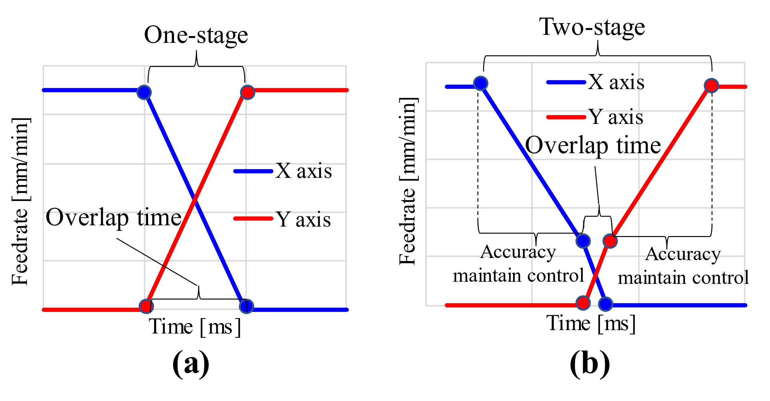
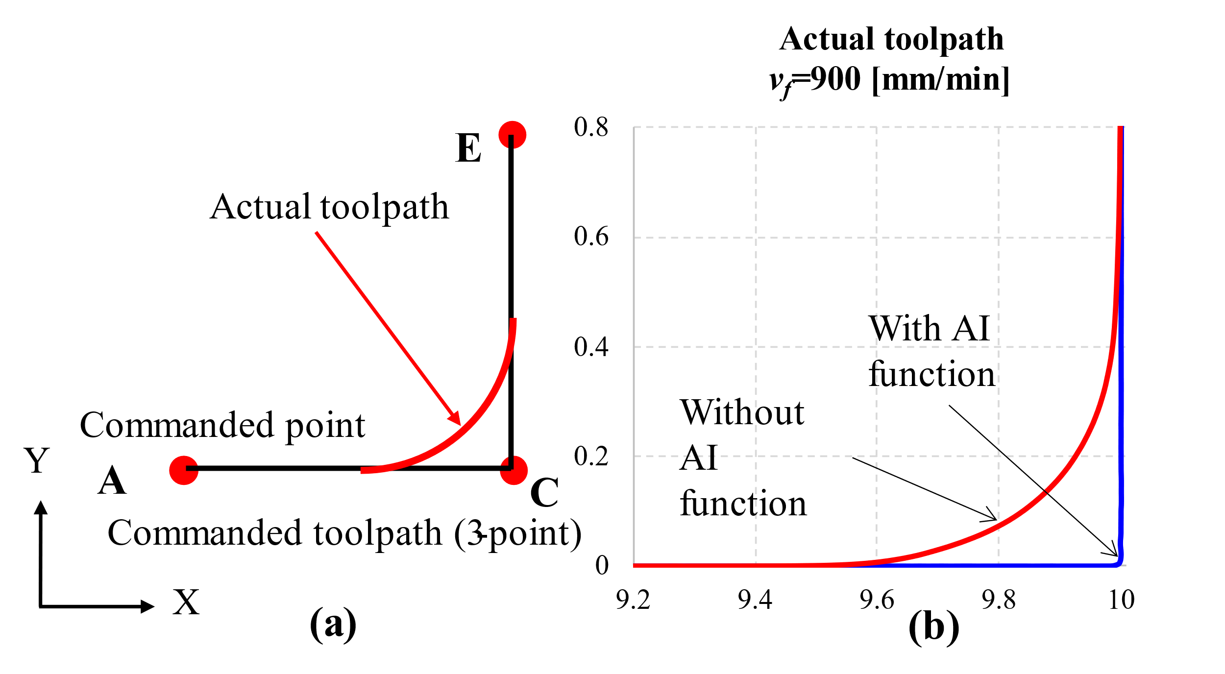
Figure 2 . (a) Programmed toolpath with three points; and (b) measurements of inner cornering error in case of AI control function is enabled (blue line) and disabled (red line)
When using AI function
Figure 3 . Comparison of predicted and measured feedrate in case the AI function is disabled (a) and enabled (b)
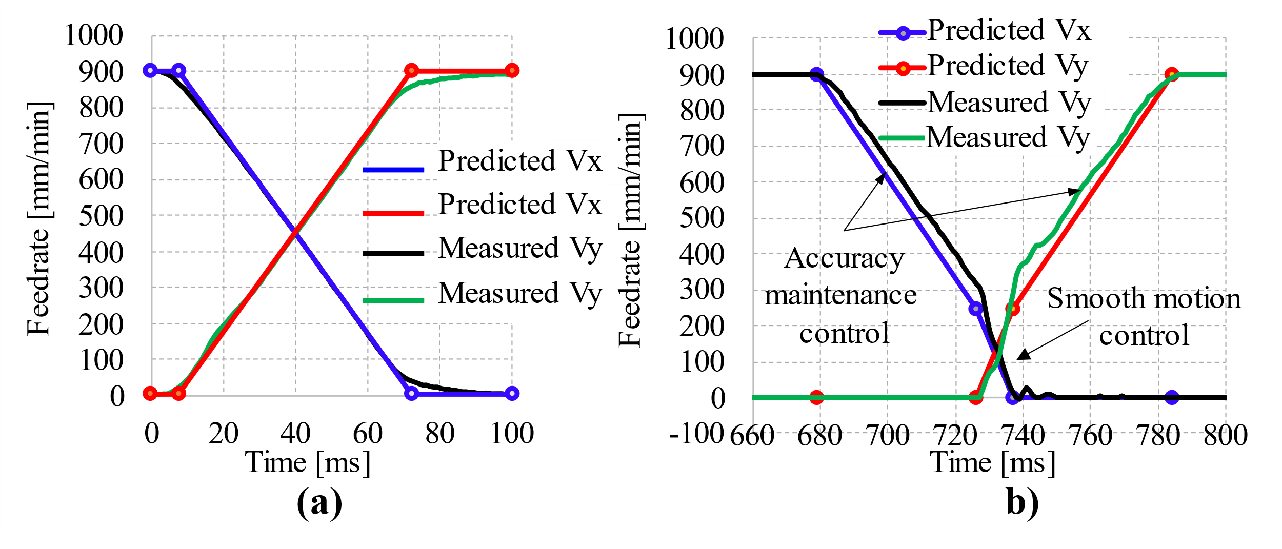
When AI function is used, the control of feedrate change is carried out approximately in two stages Figure 1 a. The first stage of deceleration in X-axis or second stage of acceleration in Y-axis is controlled without creating a toolpath error (hereafter referred to as accuracy maintenance control) and the smooth simultaneous control of each axis during the second stage of deceleration in the X-axis or the first stage of acceleration in the Y-axis leads to the generation of a toolpath error caused by overlap time (hereafter referred to as smooth movement control). The smooth movement control time was determined by the parameters set in the controller. The relationship between the programmed feedrate and the accuracy maintenance control time T ms was determined using the regression function (1) derived from the experimental values. Based on these, the actual feedrate was predicted and compared with the measured feedrate in Figure 3 to confirm the usefulness of the proposed method.
Evaluation and discussion of actual toolpath prediction
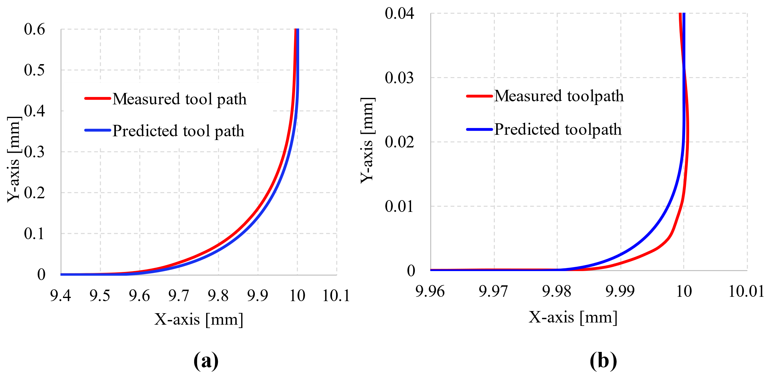
The actual toolpath was derived from the identification of the feedrate change with and without AI function Figure 4 a shows the predicted and measured toolpaths without AI function at the programmed feedrate of 900 mm/min, where the tool moves in the X direction then changes to the Y direction. Experimental results show that the difference between the two at the corner is about 15 μ m Figure 4 b shows the predicted and measured toolpaths with AI function, and the difference between the two at the corner is about 3 μ m. From these, we observed that toolpath prediction was accurate, and confirmed the usefulness of the proposed method.
Figure 4 . Comparison of predicted and measured toolpaths in case the AI function is disabled (a) and enabled (b).
Toolpath accuracy improvement method
In corner machining, there is a change in the movement direction in the programmed toolpath (for example, the tool movement on X- axis to the Y- axis in our experiment), the actual toolpath at the corner is greatly affected by the feedrate change of the machine tool ( Figure 2 a). Especially on machine tools without AI function, the inner cornering error is even larger ( Figure 2 b). In instances where the AI function is not employed, we proposed a method aimed at enhancing the accuracy of the toolpath at points of directional change point based on the identification of the actual feedrate and confirmed its usefulness through experiments.
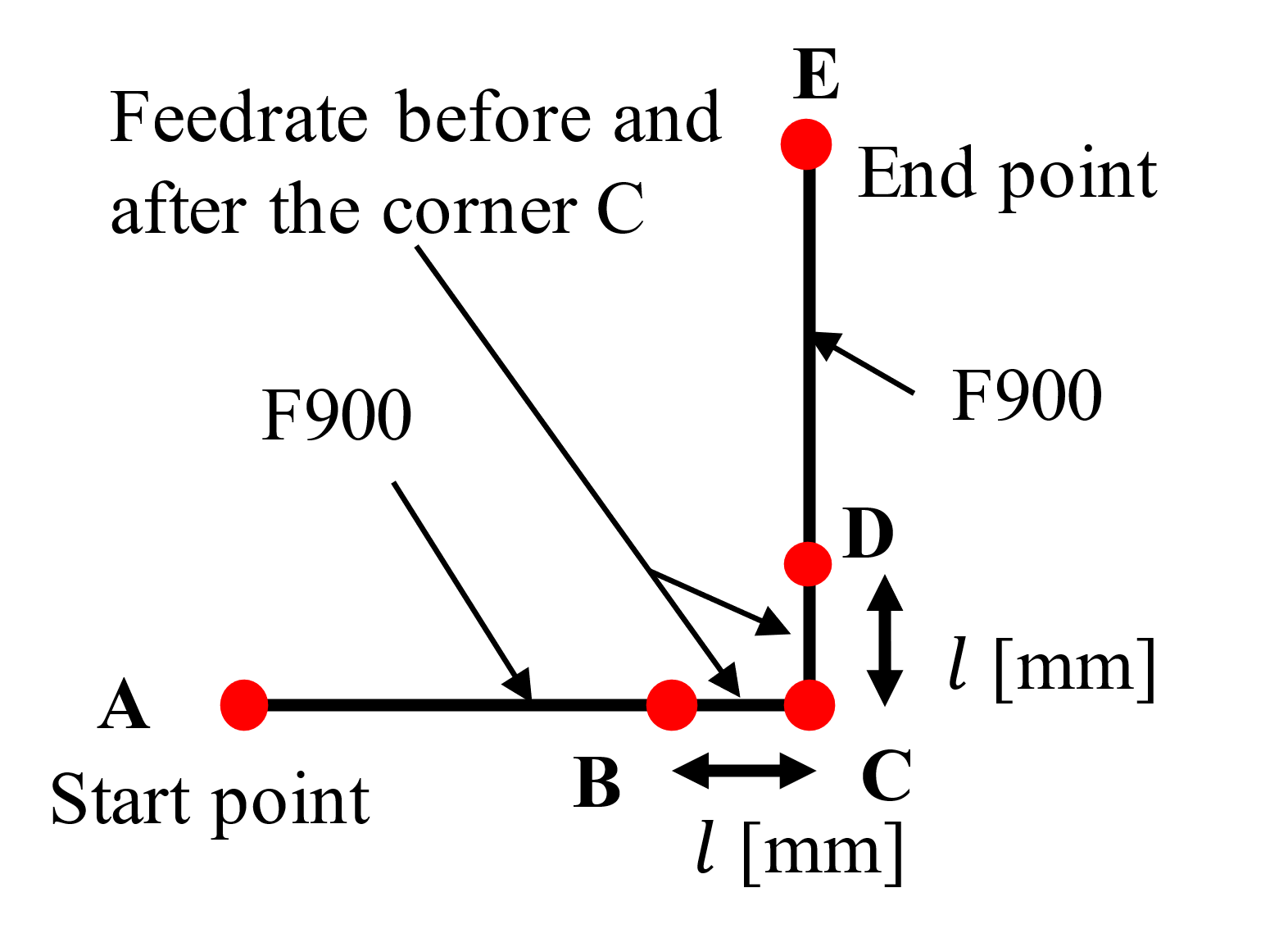
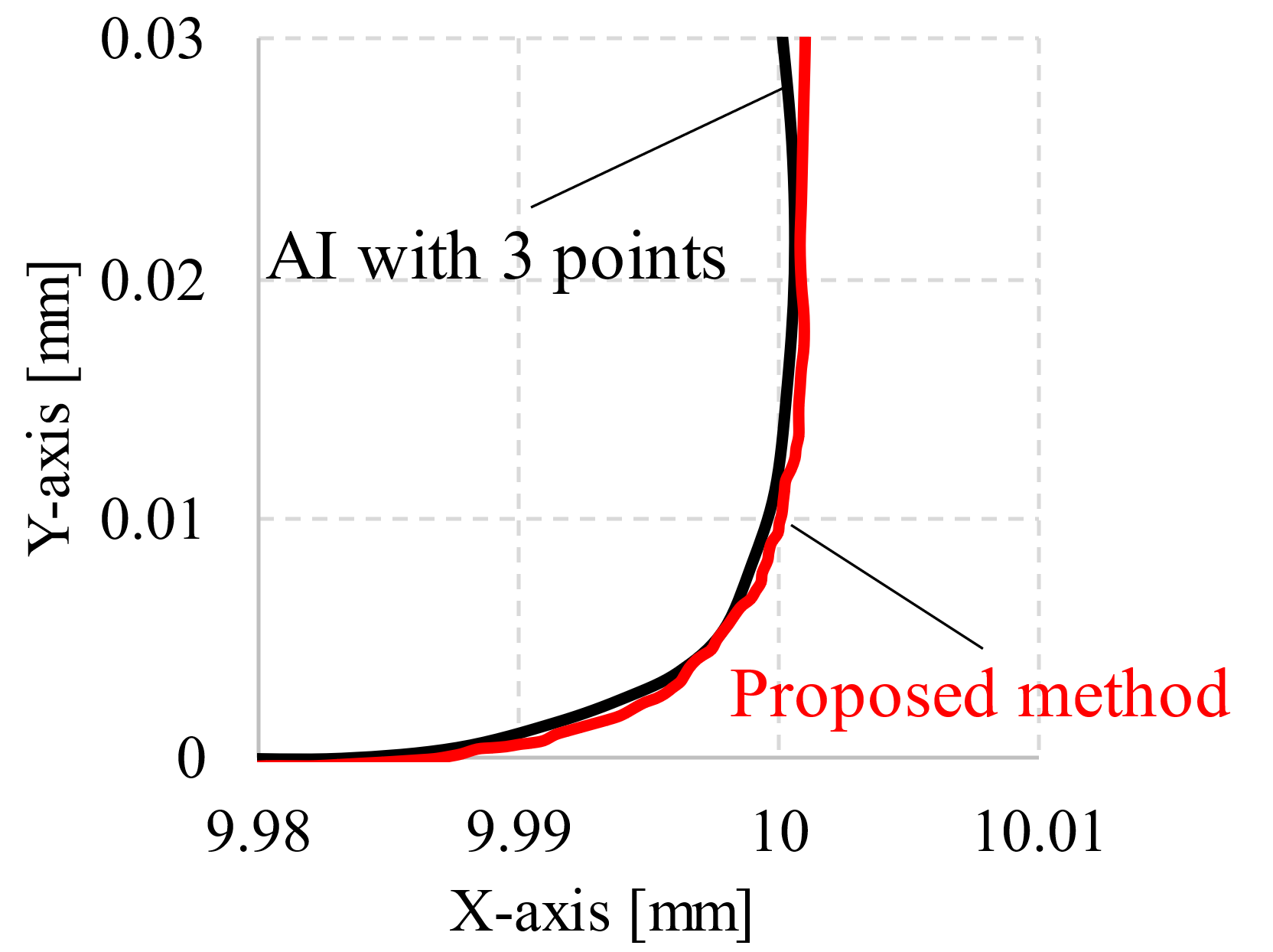
In our experiment ( Figure 1 a), the toolpath usually consists of three programmed points including the start point A, corner point C and end point E. In the proposed method, as shown in Figure 5 , the toolpath consists of five programmed points, and the programmed feedrate between BC and CD was reduced. The distance between BC and CD and the programmed feedrate are determined so that the movement time is the value set by the parameters in NC controller Figure 6 shows the measured toolpaths obtained by the proposed method and AI function. We observed that the accuracy of the measured toolpath without using AI function by the proposed method is improved, and it approximately matches the measured toolpath of three programmed point with AI function. The experimental results confirmed the usefulness of the toolpath accuracy improvement method.
Tool deflection calculation method and discussion
Overview
In this study, the tool deflection is calculated using a cantilever beam model. The deflection amount d (z) shown in Figure 7 is obtained from (2) and (3) by the cutting force F the position where the cutting force is applied a , the second moment of area I , Young's modulus, E and the tool overhang length h 6 .
When 0 ≤ z ≤ a
When a ≤ z ≤ h
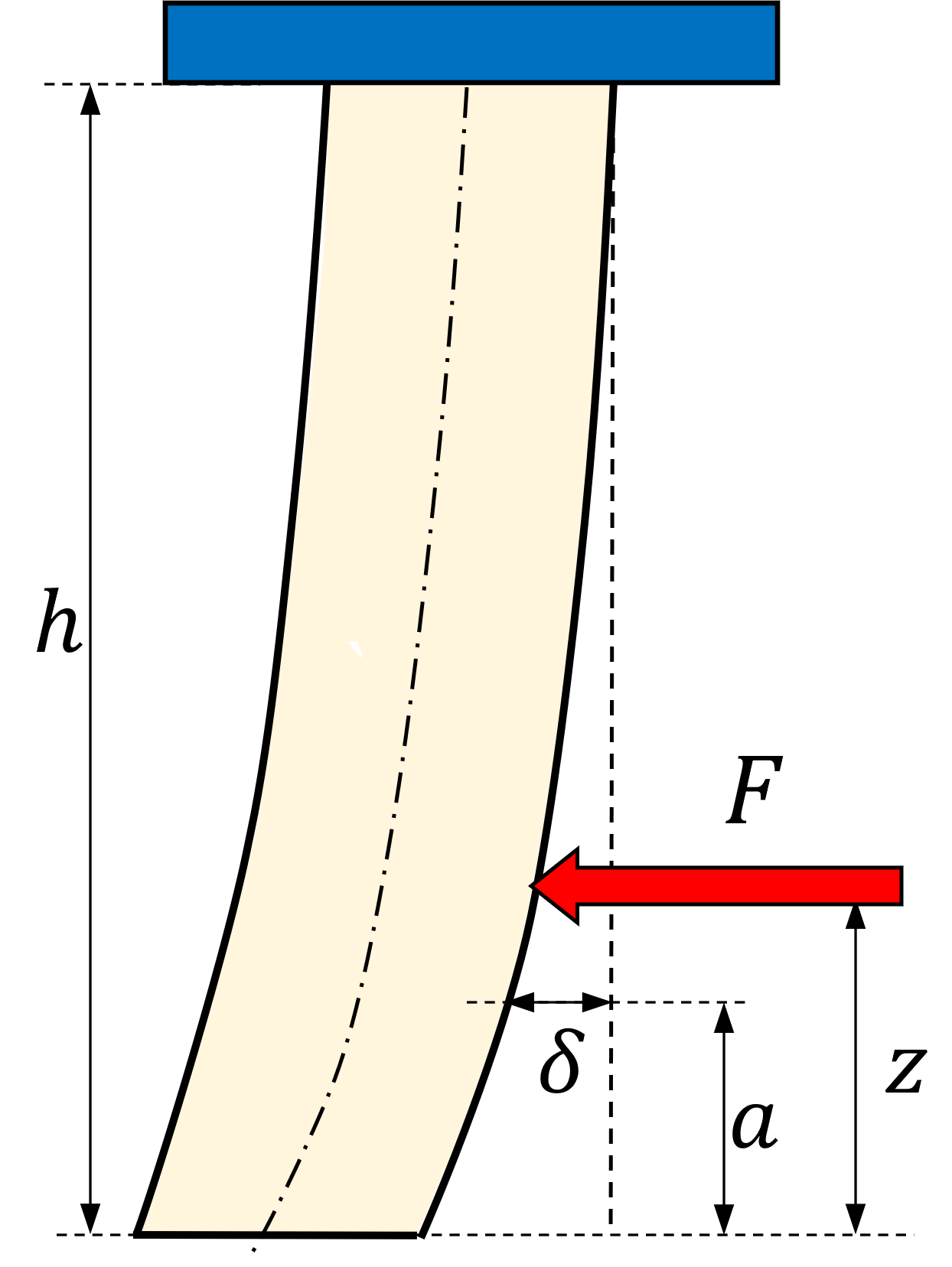
The second moment of area is determined based on the second moment of area of the cantilever. Because the shape of the cutting-edge part is complex, it is difficult to calculate accurately the second moment of area. According to a study by Fujii et al. 6 , L.Kops et al. 7 , the second moment of area of the square end mill is equal to a cylinder 0.8 times the tool diameter. The second moment of area I [mm 4 ] of the tool diameter d [mm] can be represented by the following (4).
Cutting force calculation method
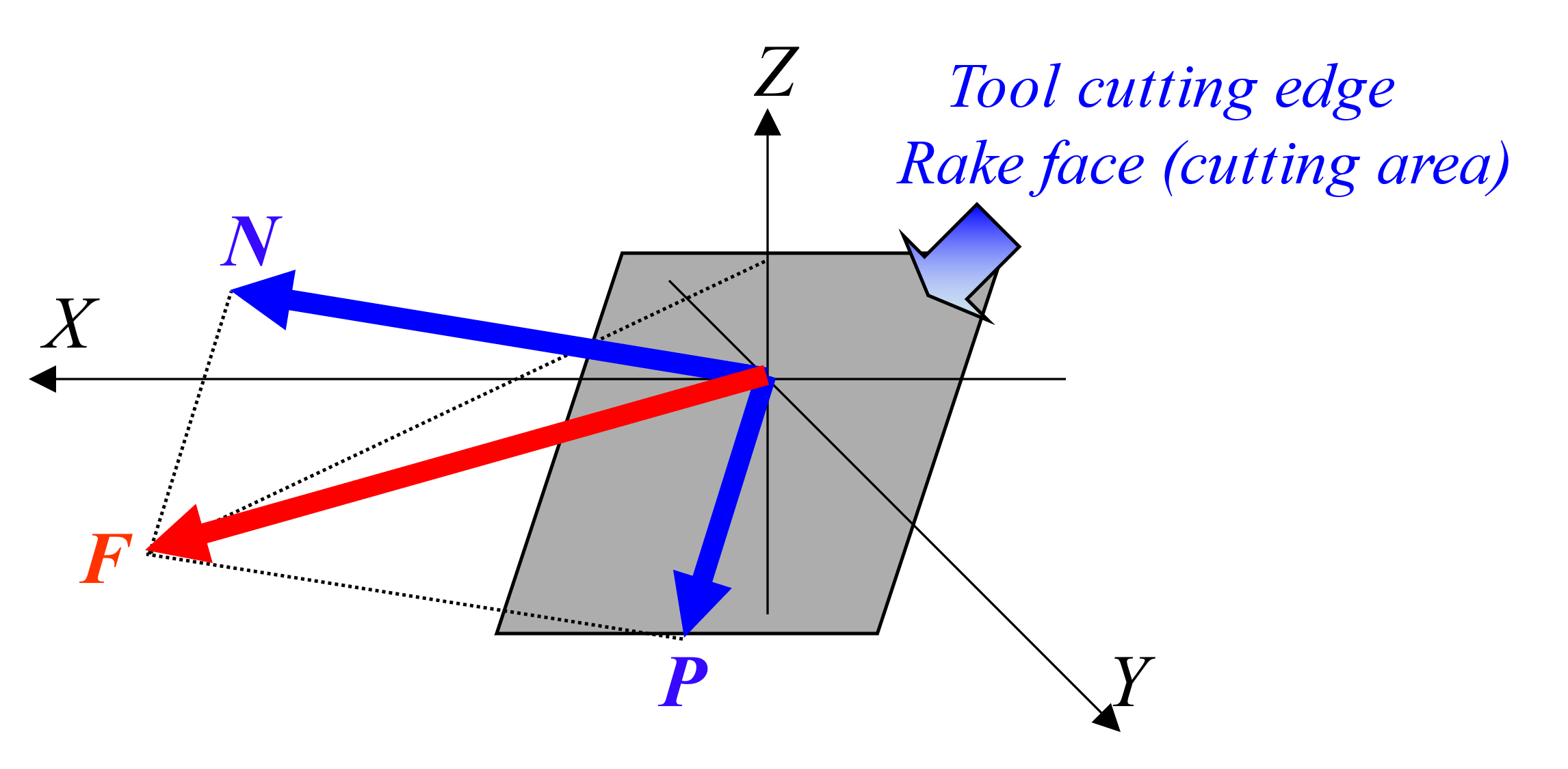
The cutting force F is obtained as the resultant force of the force N applying on the rake face and the frictional force μN , as shown in (5). As shown in Figure 9 , the force N applying perpendicular to the rake face of cutting tool is calculated from the cutting area S and the cutting force coefficient K S as shown in (6). The cutting area S is obtained from the axial depth of cut, radial depth of cut, diameter of the cutting tool, helix angle, and feed per tooth.
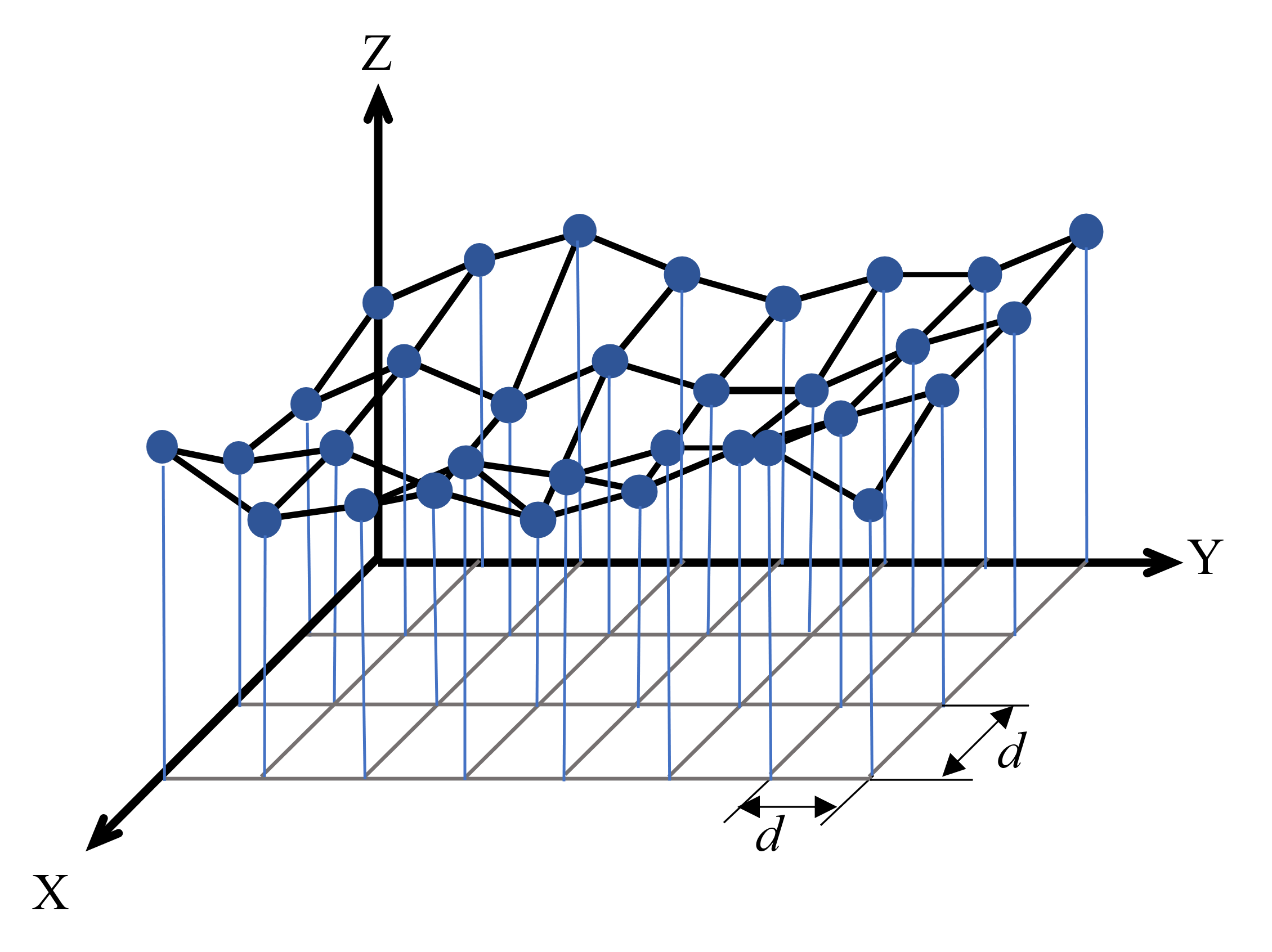
In actual machining, the cutting area changes due to the curvature variance of curved surface. Therefore, the machining simulation is performed, and the cutting area of the cutting tool and the workpiece is derived at the tool position and the cutting-edge rotation angle. The simulation method is constructed with a relatively simple Z-map model. As shown in Figure 8 , the Z-map model is a two-dimensional array (X and Y grid points by a meshing operation) that stores the Z-value of each grid point according to the cutter tooth position during the milling process. In Figure 8 , d is the grid size, and a smaller value will result in higher accuracy but a longer calculation time. The grid size is 10 µ m which is a balance between the required accuracy and calculation time.
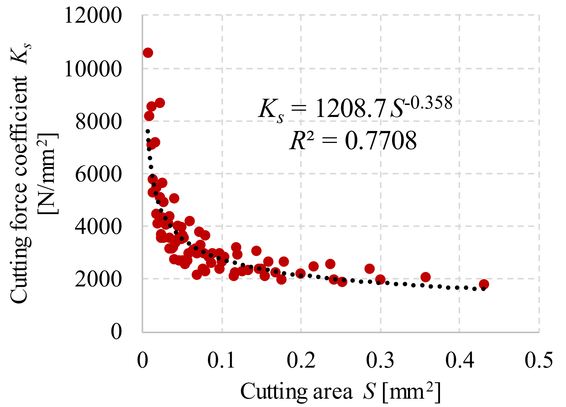
The axial depth of cut and the radial depth of cut are calculated using the Z-map model. As shown in Figure 10 , the cutting force coefficient K S is obtained from the approximate formula determined from the measured cutting force in cutting experiment.
Evaluation and discussion of the tool deflection calculation method
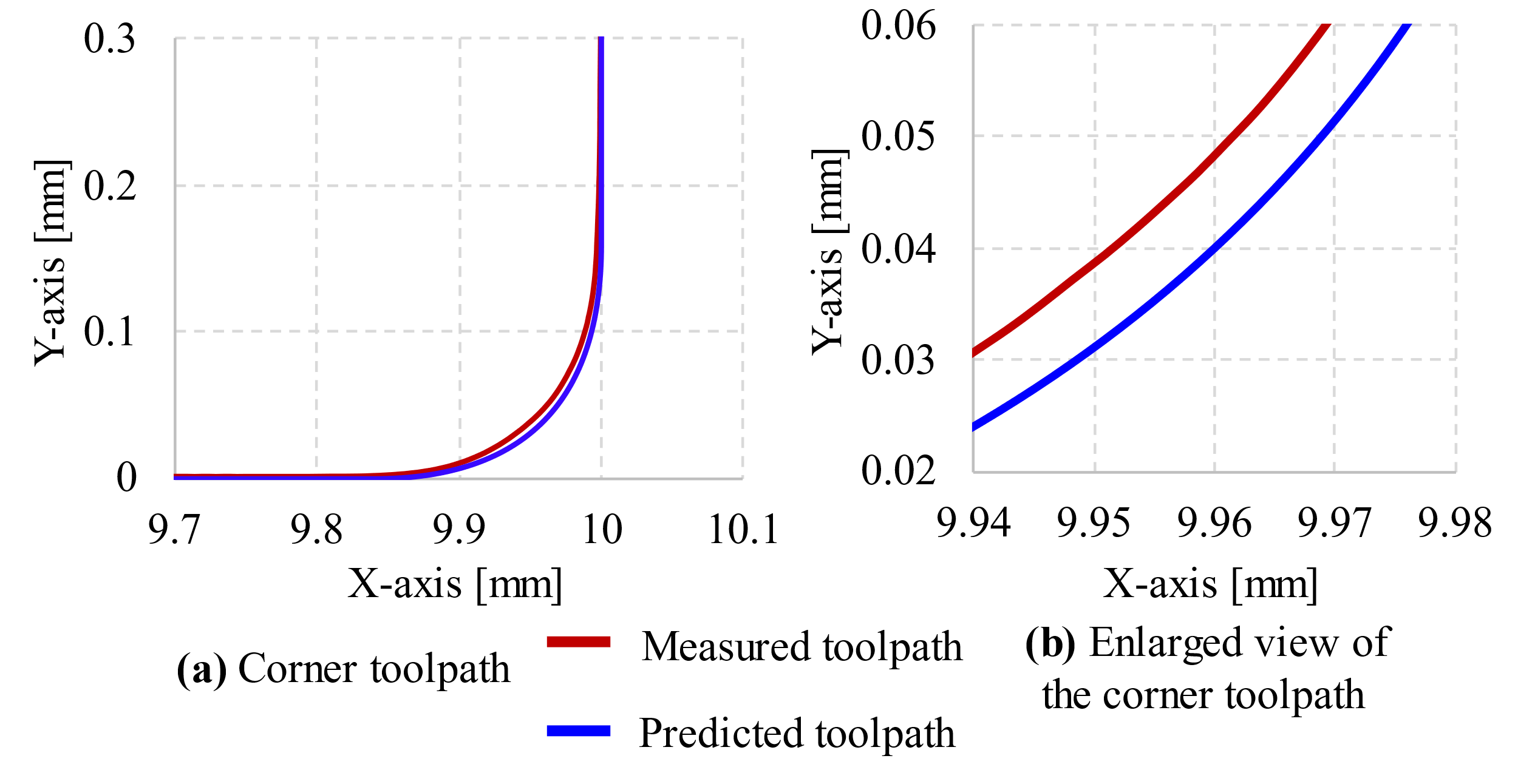
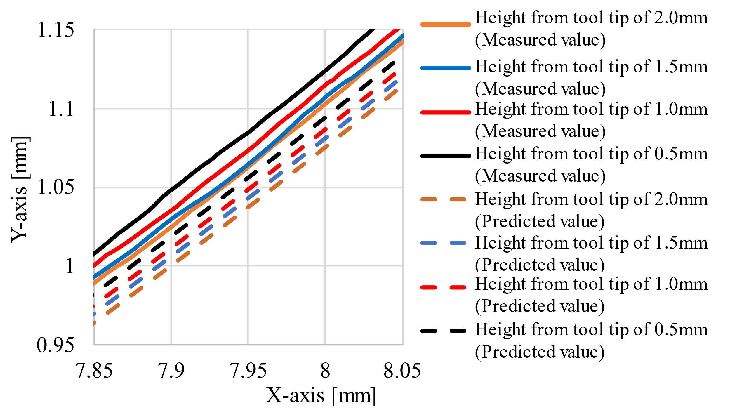
The machined surface was predicted from the tool deflection calculated based on the predicted actual toolpath and feedrate obtained by proposed method. The experimental conditions were a square-end mill with a tool diameter of 10 mm and a helix angle of 30°, a workpiece S55C, a rotation speed of 2000 rpm, an axial depth of cut of 2.5 mm, a radial depth of cut of 2.0 mm, a feedrate of 300 mm/min, a tool overhang length of 50mm. The corner path was set to move the tool in the positive direction of the X-axis and change the angle by 90° in the positive direction of the Y-axis at the corner point Figure 11 a shows the predicted toolpath and the measured toolpath at the corner when AI function is not used, and Figure 11 b shows the enlarged view of the toolpath at the corner. The prediction error at the corner is about 8 μ m. The machined shape was predicted using this predicted toolpath and the tool deflection amount considering the feedrate change. The coordinate measuring machine (CMM) was used to measure the machined shape of the workpiece. The measurement points were those where the heights from the tool tip were 0.5, 1.0, 1.5, and 2.0 mm and were in contact with the workpiece Figure 12 shows the predicted machined shape and the measured machined shape at different heights from the tool tip when AI contour control is not used, and the maximum error is about 20 μ m. This error is considered to be mainly due to the toolpath prediction error. This confirmed the usefulness of the tool deflection calculation method.
Results and discussion on the machining accuracy enhancement method
We proposed a method for improving machining accuracy by correcting the amount of tool deflection in side milling with a square-end mill. In this study, the amount of tool deflection was corrected by rotating the B-axis in the five-axis machine tool.
The tool deflection amount increases approximately linearly with the tool overhange length. Therefore, in the proposed method, the B-axis is rotated by the angle of the tool axis, which changes according to the amount of deflection generated at the tool tip.
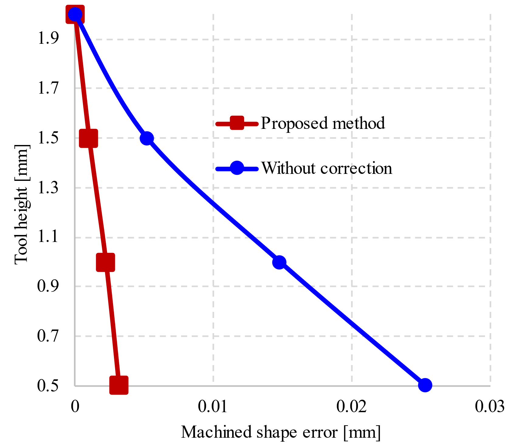
Figure 13 shows the measured machined shape of the workpiece with and without angle correction at the height from the tool tip of 0.5 mm to 2.0 mm. The machined shape error without angle correction is about 25 μ m at the height from the tool tip of 0.5mm, whereas it is about 3 μ m in the proposed method. From this, the machining by the proposed method reduced the machining error between the tool heights caused by tool deflection, and confirmed its usefulness.
Conclusion
In this study, with the aim of improving the accuracy of machining by NC machine tools, we identified the actual feedrate based on the Acc/Dec processing of the machine tool, and proposed a toolpath accuracy enhancement method based on the identification method. We also proposed a method for enhancing machining accuracy by compensating the machined shape error based on the tool deflection calculation method. The following results are presented below.
We identified the actual feedrate considering the Acc/Dec characteristic control of the machine tool, both with and without using the AI function. Comparison of the measured feedrate and predicted feedrate obtained by proposed method showed the usefulness of the identification method of the actual feedrate change.
A method was proposed to improve the accuracy of the toolpath at directional changes during movement by identifying actual changes in feedrate, which was validated through experimental confirmation, particularly when the AI function is disabled.
We also proposed a tool deflection calculation method for square-end mill tools, which calculates the tool deflection from the cutting force. The tool deflection calculated by the proposed method was used to predict the machined shape, and compared with the machined shape measured in the machining experiment under the same conditions, the usefulness of the tool deflection calculation method was demonstrated.
A method for improving machining accuracy by correcting the amount of tool deflection in side milling with a square-end mill was proposed. The effectiveness of the machining accuracy enhancement method was confirmed by comparing the measured machining shape with proposed method and without angle correction.
LIST OF ABBREVIATIONS
Acc/Dec: Acceleration and Deceleration.
AI: Artificial Intelligence.
CAD: Computer-Aided Design.
CAM: Computer-Aided Manufacturing.
CAPP: Computer-Aided Production Planning
CMM: Coordinate Measuring Machine.
CNC: Computer Numerical Control.
Acknowledgements
We acknowledge the support of time and facilities from the HCMUT (VNU-HCM).
CONFLICT OF INTEREST
The authors declare that they have no competing interests.
AUTHOR CONTRIBUTION
Than Trong Khanh Dat: Conceptualization, Investigation, Methodology, Manuscript Preparation, Validation and Manuscript Editing.
Tran Thien Phuc: Investigation, Methodology, Validation and Manuscript Editing.
References
- Otsuki T., Sasahara H., Sato R.. Method to evaluate speed and accuracy performance of CNC machine tools by speed-error 2-D representation. Journal of Advanced Mechanical Design, Systems, and Manufacturing. 2019;13(1):. Google Scholar
- Otsuki T., Sasahara H., R. Sato. Method for generating CNC programs based on block-processing time to improve speed and accuracy of machining curved shapes. Precision Engineering. 2019;55:33-41. Google Scholar
- Qiu H., Yamaguchi T., Huang Y.. Motion error estimation of linear interpolation cutter path of machining center produced by NC linear acceleration/deceleration processing. Transactions of the JSME (in Japanese). 2023;89(920):. Google Scholar
- T. Yamazaki, Seto M., Tsutsumi M.. Design of Acceleration and Deceleration Commands for NC Machine Tools. Journal of the Japan Society for Precision Engineering. 2000;66(8):1260-1264. Google Scholar
- Y. Fujii, Iwabe Y.. Cross-sections and Flexural Rigidity of Helical End Mills. Precision Machinery - The Japan Society for Precision Engineering. 1983;49(6):735-740. Google Scholar
- Nakagawa H., Hirogaki T., Nakayama M., Otsuka Hirotoshi. High Precision Machining with Multi-flute End-mill tool on 5-Axis Controlled Machining Center Achievement of Constant Cutting Force in Side milling by Controlling Axial Depth of Cut. Journal of the Japan Society for Precision Engineering. 2003;69(3):385-389. Google Scholar
- L. Kops, Vo D.. Determination of the equivalent diameter of an end mill based on its compliance. CIRP annals. 1990;39(1):93-96. Google Scholar